Evaluation Board
This evaluation board is only can be used with P4M-440G.
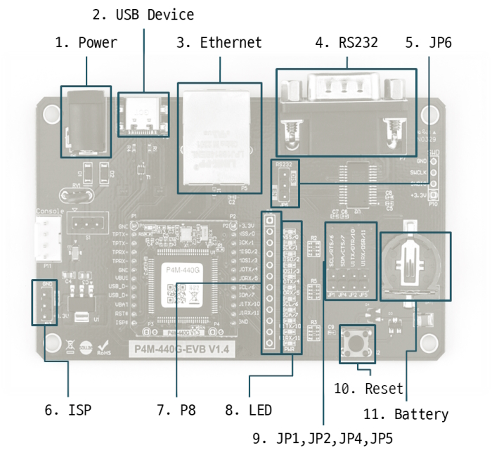
1. Power
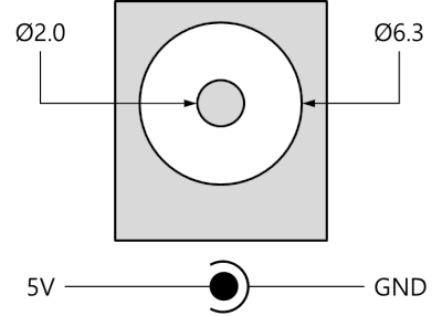
This is the power input port that supplies power to the board. The input voltage is DC 5V, and the port specifications are as follows:
2. USB Device Port for connection with PC
The USB device port is to connect with PC. You can access to P4M-440G via the development tool(PHPoC Debugger) by connecting USB cable to this port. You can supply DC 5V power through this port.
3. Ethernet
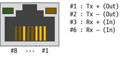
This port provides 10/100Base-TX Ethernet interface of P4M-440G. This port is equipped with an RJ45 connector and is mapped to the NET0 device for programming purposes.
4. RS232

This port uses a D-SUB 9-pin male connector and is mapped to the UART0 device for programming purposes. The pin specifications are as follows:
| Pin | Name | Description | Level | I/O | Wiring |
|---|---|---|---|---|---|
| 2 | RXD | Receive Data | RS232 | In | Required |
| 3 | TXD | Transmit Data | RS232 | Out | Required |
| 4 | DTR | Data Terminal Ready | RS232 | Out | Optional |
| 5 | GND | Ground | Ground | - | Required |
| 6 | DSR | Data Set Ready | RS232 | In | Optional |
| 7 | RTS | Request To Send | RS232 | Out | Optional |
| 8 | CTS | Clear To Send | RS232 | In | Optional |
5. JP6
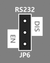
JP6 enables or disables the RS232 port on the board. Connecting the jumper to the "EN" side activates it, while connecting it to the "DIS" side or leaving it unconnected deactivates it.
6. ISP Jumper
You connect +3.3V or GND to the ISP# pin of the P4M-440G using this jumper.
7. P8
P8 is connected 1:1 with all the pins on the module's P2.
| Pin | Name | I/O | Description |
|---|---|---|---|
| P8.1 | +3.3V | - | +3.3V Power Input |
| P8.2 | NSS(0.0) | In/Out | UIO 0.0 / SPI NSS |
| P8.3 | SCK(0.1) | In/Out | UIO 0.1 / SPI SCK |
| P8.4 | MISO(0.2) | In/Out | UIO 0.2 / SPI MISO |
| P8.5 | MOSI(0.3) | In/Out | UIO 0.3 / SPI MOSI |
| P8.6 | U0TX(0.4) | In/Out | UIO 0.4 / UART0 TX |
| P8.7 | U0RX(0.5) | In/Out | UIO 0.5 / UART0 RX |
| P8.8 | SCL(0.6) | In/Out | UIO 0.6 / I2C SCL |
| P8.9 | SDA(0.7) | In/Out | UIO 0.7 / I2C SDA |
| P8.10 | U1TX(0.10) | In/Out | UIO 0.10 / UART1 TX |
| P8.11 | U1RX(0.11) | In/Out | UIO 0.11 / UART1 RX |
| P8.12 | GND | - | Ground |
8. LED
| LED | Color | Description |
|---|---|---|
| NSS/0 | Green | ON when UIO 0.0 is LOW |
| SCK/1 | Green | ON when UIO 0.1 is LOW |
| MISO/2 | Green | ON when UIO 0.2 is LOW |
| MOSI/3 | Green | ON when UIO 0.3 is LOW |
| U0TX/4 | Green | ON when UIO 0.4 is LOW |
| U0RX/5 | Green | ON when UIO 0.5 is LOW |
| SCL/6 | Green | ON when UIO 0.6 is LOW |
| SDA/7 | Green | ON when UIO 0.7 is LOW |
| U1TX/10 | Green | ON when UIO 0.10 is LOW |
| U1RX/11 | Green | ON when UIO 0.11 is LOW |
| PWR | Red | ON when the power is supplied |
9. JP1, JP2, JP4, JP5
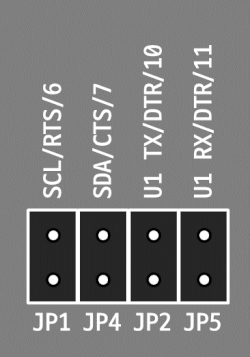
These jumpers are used to connect each control signal (RTS, CTS, DTR, DSR) of RS232 to the RS232 port.
| Name | Description |
|---|---|
| JP1 | Jumper Connection: Connect P2.8 (SCL, 0.6) pin to RS232 port 7. |
| JP4 | Jumper Connection: Connect P2.9 (SDA, 0.7) pin to RS232 port 8. |
| JP2 | Jumper Connection: Connect P2.10 (U1TX, 0.10) pin to RS232 port 4. |
| JP5 | Jumper Connection: Connect P2.11 (U1RX, 0.11) pin to RS232 port 6. |
10. Reset Button
If this button is pressed, LOW signal is connected to the RESET# pin.
11. Battery Socket
This is a battery socket for the RTC. Please use a CR1225 or CR1220 battery.