Layout
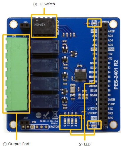
1. Output Ports
Output ports are interfaced with a 5mm spaced terminal block which has 8 terminals. Every output port is connected to a relay which is NO (Normal Open) type.
※ Normal Open: This means the default state of output port is OFF.
Output ports' range of use is as follows:
| Voltage (DC) | Max. Permissible Current |
|---|---|
| 30V | 2A |
※ Caution: It may result in product malfunction to use beyond the maximum permissible current. Be sure to use it considering the peak current of a connected device.
※ Note: The maximum number of PES-2401 which can be connected to one PHPoC board is 4.
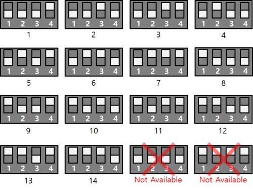
2. SLAVE ID Switch
A slave ID is used when PHPoC board identifies each smart expansion board. So, each smart expansion board, which is connected to a PHPoC board, should have an unique slave ID. The slave ID can be set one of the numbers from 1 to 14 by 4 DIP switches as follows:
3. LED
STS LED
PES-2401 has two STS LEDs. The one on the top of JP1 is connected to 3.3V and the other one on the bottom is connected to 5V. The operation of the two LEDs is the same as the following.
| state | LED operation |
|---|---|
| normal | repeat on and off every second |
| invalid slave ID | blinks very quickly |
| fail to communicate with PHPoC | off |
Digital Output Port LED
PES-2401 has 4 LEDs of digital output ports
| LED | Description |
|---|---|
| 0 | turned ON with output 0 is ON |
| 1 | turned ON with output 1 is ON |
| 2 | turned ON with output 2 is ON |
| 3 | turned ON with output 3 is ON |