Layout
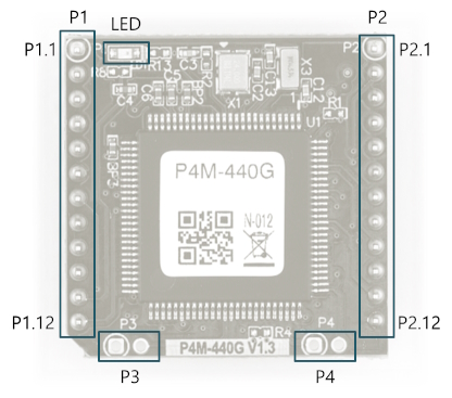
P4M-440G interfaces with two 12 x 1 pin headers (P1 ~ P2). The pin spacing is 2mm.
P1
| Pin# | Name | I/O | Description |
|---|---|---|---|
| P1.1 | GND | - | Ground |
| P1.2 | TPTX+ | In/Out | Ethernet Transmit + |
| P1.3 | TPTX- | In/Out | Ethernet Transmit - |
| P1.4 | TPRX+ | In/Out | Ethernet Receive + |
| P1.5 | TPRX- | In/Out | Ethernet Receive - |
| P1.6 | GND | - | Ground |
| P1.7 | VBUS | In | USB Device VBUS |
| P1.8 | USB_D_D- | In/Out | USB Device Data - |
| P1.9 | USB_D_D+ | In/Out | USB Device Data + |
| P1.10 | VBAT | In | Battery Input |
| P1.11 | RST# | In | Reset Input (Active LOW) |
| P1.12 | ISP# | In | ISP Input (Active LOW) |
P2
| Pin# | Name | I/O | Description |
|---|---|---|---|
| P2.1 | +3.3V | - | +3.3V Power Input |
| P2.2 | NSS(0.0) | In/Out | Reserved |
| P2.3 | SCK(0.1) | In/Out | Reserved |
| P2.4 | MISO(0.2) | In/Out | Reserved |
| P2.5 | MOSI(0.3) | In/Out | Reserved |
| P2.6 | U0TX(0.4) | In/Out | UIO 0.4 / UART0 TX |
| P2.7 | U0RX(0.5) | In/Out | UIO 0.5 / UART0 RX |
| P2.8 | SCL(0.6) | In/Out | Reserved |
| P2.9 | SDA(0.7) | In/Out | Reserved |
| P2.10 | U1TX(0.10) | In/Out | UIO 0.10 / UART1 TX |
| P2.11 | U1RX(0.11) | In/Out | UIO 0.11 / UART1 RX |
| P2.12 | GND | - | Ground |
LED
There is an STS LED located at the top-left corner of the module. This LED blinks at a 1-second interval.
P3, P4
P3 and P4 are only for the manufacture.